
This article was published in IEEE Communication Society Bangalore India Newsletter, Issue 9, June 2021
It is a common knowledge for LTE practitioners that for a baseband signal bandwidth (BW) of 20MHz the minimum sampling rate for converting this signal to digital domain is 30.72MHz. This number of 30.72MHz appears in 3GPP LTE specifications document, for example in TS 36.101.
The sampling rate of 30.72MHz is not intuitive and there are 2 questions which may arise in the mind of first-time reader. Firstly, how can a signal with bandwidth of 20MHz be sampled at 30.72MHz? Does it not violate the fundamental Nyquist sampling theorem which states that sampling rate should be at least twice of signal bandwidth? Secondly, why 30.72MHz and why not use a rather well-rounded number like 30MHz or 40MHz?
The answer to first question is ‘quadrature sampling’. An LTE transceiver is a quadrature system as shown in Figure-1.
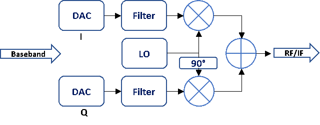
Figure-1: Quadrature Transmitter System
The I and Q paths in a quadrature system has its own mixers, filters for processing the signal. An LTE signal of BW 20MHz refers to this quadrature or complex signal bandwidth where individual I and Q paths carry signal within a bandwidth of 10MHz and when combined provide the total 20MHz bandwidth. For each of the paths with 10MHz bandwidth the sampling rate of 30.72MHz very well exceeds (3x) the Nyquist sampling rate.
The second question can be addressed by recalling the LTE transmitter and receiver design which is based on OFDM and how the sub-carriers are generated. Consider the case of OFDM transmitter. The inverse discrete fourier transform (IDFT) or the efficient form of DFT, the inverse fast fourier transform (IFFT) is used to generate multiple sub-carriers. Consider the IDFT equation shown in Equation-1.
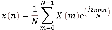
Equation-1: IDFT Equation
You can edit text on your website by double clicking on a text box on your website. Alternatively, when you select a text box a settings menu will appear. your website by double clicking on a text box on your website. Alternatively, when you select a text box.
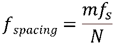
Equation-2: Frequency spacing calculation
fspacing in Equation-2 gives the spacing between 2 neighboring frequencies in a N frequency system. m is an integer which goes from 1 to N which gives the index of each frequency point.
Consider an LTE signal with BW="20MHz" and sub-carrier spacing (SCS) of 15kHz. The number of sub-carriers within 20MHz BW spaced at 15kHz is calculated by dividing the BW by SCS which gives 1333.33 sub-carriers. This value is higher than the actual number of sub carriers specified by 3GPP specifications for LTE (1200 sub-carriers) and 5G-NR (1272 sub carriers). Equation-1 is used to generate these sub-carriers but the actual implementation uses radix-2 FFT where the number of frequency points in FFT should be a power of 2. Thus, to generate 1200 sub-carriers, 211 FFT is used. This gives the value of N as 211 or 2048 sub-carriers.
Rearranging Equation-2 as below:

Equation-3: Sampling rate calculation
In OFDM transceiver, identifying fspacing as SCS which is 15kHz, N="2048" and m="1" (always use 1 since there is no indexing in this context) the sampling rate is calculated to be fs=30.72MHz which answers the second question.
Equation-3 can be applied to calculate sampling rates for other LTE and 5G-NR BW and SCS cases as shown in Table-1.
| SCS (kHz) | BW (MHz) | N | fs (MHz) |
| 60 | 100 | 2048 | 122.88 |
| 15 | 5 | 512 | 7.68 |
| 15 | 40 | 4096 | 61.44 |
Table-1: Sampling rates for different SCS and BW cases